Piles are used to support several types of structures, from multi-family buildings to wind turbine foundations or offshore platforms for oil and gas extraction. That is why understanding the interaction between the pile and the foundation soil is fundamental to their design. Do yo want to know more? Continue reading...
Content
What are piles
As Atkinson (2007) points out, a simple way to understand what a pile is, is to think of them as thin columns installed within the ground, often in groups. The main purpose of these elements is to transfer loads from the structure to a layer of greater strength and stiffness located at some depth below the ground surface.
Piles are typically constructed in steel or reinforced concrete, and can be driven into the ground (as is usually the case with steel piles), or they can be cast in situ into a drilling hole (as is usually the case with reinforced concrete piles).
Figure 1, taken from Atkinson (2007), illustrates some typical pile configurations. Part a) shows a pile supported on a stratum of high stiffness, so that most of its resistance is provided by its toe; part b) corresponds to a pile that resists the load predominantly by friction between the surrounding soil and its shaft, as often occurs in soils that have considerable thicknesses of compressible soils and a very deep stiff stratum; part c) represents inclined piles, thus installed to resist significant lateral loads; and part d) shows a group of piles, a configuration used when the loads transmitted by the superstructure are too high to be absorbed by a single element.
In most projects, deep foundations are a solution that is applied after analyzing all possible alternatives associated with shallow foundations, because such shallow foundations are simpler to construct and more economical in most cases.
Figure 1 Typical pile configurations (Source: modified from Atkinson, 2007).
Regarding the economic part, Coduto (2001) offers a rule-of-thumb applicable to the case of buildings: usually, shallow foundations cease to be economically viable for a project when the total area of the foundations exceeds one third of the floor area of the building. It is just a number to take into account for preliminary estimates, but it serves to have a good order of magnitude.
Load transfer from the pile to the ground
The mechanism of load transfer from a pile to the ground has been studied by numerous researchers over the years, given the high complexity of the subject. Figure 2 shows a pile subjected to a load Q, which is resisted by the force at the toe or base Qb and by Qs, which is the force per shaft due to the shear stress generated between the pile material and the soil. Thus, it follows that:
Q = Qb + Qs
The same figure shows the load-settlement curves, differentiating the components contributed by the base and by the shaft when the pile is stressed by an external load.
Figure 2 An individual pile (Source: Atkinson, 2007).
Das (2012), points out that if the load Q is increased gradually (as is usual in most civil projects), the maximum frictional resistance along the shaft will be fully mobilized when the relative displacement between the soil and the pile is of the order of 5 mm to 10 mm, irrespective of the pile size and length. However, the toe resistance Qb will not be mobilized until the pile toe has moved approximately 10% to 25% of its diameter (the first value corresponds to driven piles, and the second to excavated and cast-in-place piles).
This implies that, in order for the pile to resist the load, it must necessarily move, settle. This may seem strange to those who think that piles do not move, but the fact is that they always experiment some deformation. And that, moreover, it is precisely this deformation that sets in motion their load resisting mechanism.
Practical application: load test on an instrumented pile
According to the above, the shaft resistance Qs is developed by a considerably smaller displacement of the pile, with respect to that needed to develop the toe load Qb. In order to analyze this fact, let us review the results of a pile loading test, performed in the distant 1970 by Mansur & Hunter, and reported by Das (2012).
Part a) of Figure 3 shows the load-settlement curve obtained for the tested pile, whose main characteristics are shown in the same graph. Part b), includes information on the shaft resistance developed for different settlement levels, as reported by the aforementioned authors
Figure 3 Mansur & Hunter (1970) load test results: a) load-settlement curve; b) mobilized Qs curves for different levels of settlement. (Source: modified from Das, 2012).
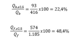
Based on part b) of the previous figure, for a settlement s = 2.5 mm, Q = 667 kN (applied a the surface), Qb,s2,5 = 93 kN and Qf,s2,5 = 574 kN. Thus, relating these values to the total resistances per point and per shaft obtained in the test, we have:
Based on these results, it is obvious that the shaft strength mobilizes much faster than the toe strength.
Understanding the mechanism of load transfer from the pile to the ground, it is evident the need to properly estimate the geomechanical design parameters to be used in the analysis of deep foundations, in order to obtain realistic values of the resistance related with toe and shaft. That is why in a future post we will review this topic...
References
Atkinson, J. (2007) “The Mechanics of Soils and Foundations”. Second Edition. CRC Press – Taylor & Francis Group. Abingdon, UK.
Coduto, D. (2001) “Foundation Design: Principles and Practice”. Second Edition. Prentice Hall. New Jersey, USA.
Das, B. (2012) “Fundamentos de Ingeniería de Cimentaciones”. Séptima Edición. CENGAGE Learning Editores, S.A. México D.F, México.